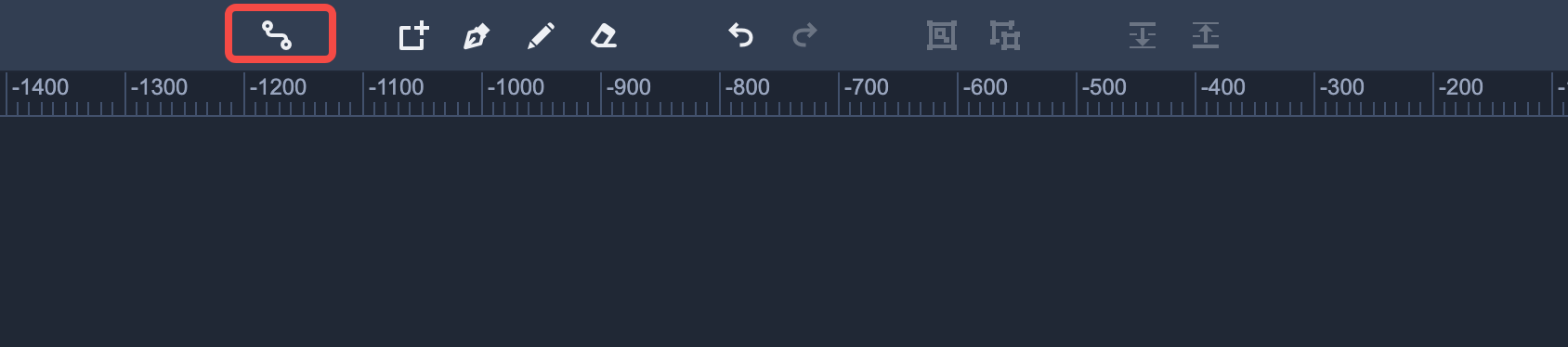
Click "Connect Mode" in the top toolbar to enter the mode.
To exit the mode, click "Connect Mode" again or press "Esc" key.
In this mode, every component is displayed with four connection points.
Dragging one connection point to a target component helps you connect these two components together. A connector will also be generated automatically.
Please note: Connectors are smart lines that you can use to connect any two components in your flow charts. Once a connector is created, selecting the connector shows four line control points. You can then drag these control points to readjust the connector.